Hello guys,
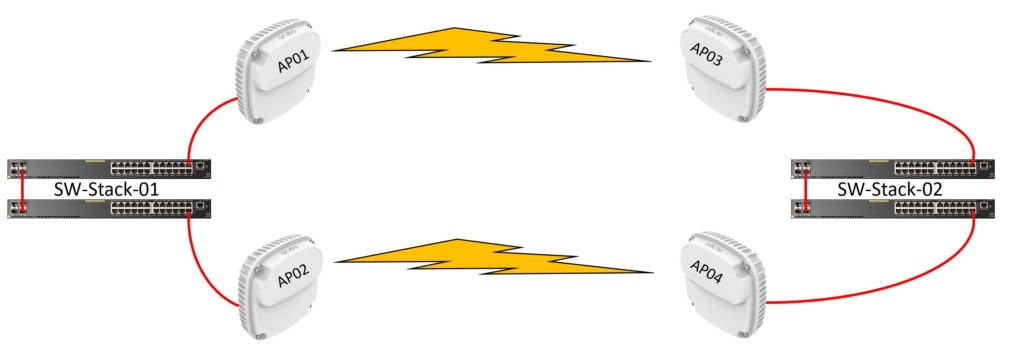
today I want to tell you how to create a redundant point-to-point connection with Aruba 387 access points.
Update
for this setup the firmware version 8.6.0.6 or newer is absolutely needed. Because in the older versions the bug AOS-216445 is not fixed yet.
AOS-216445
Clients connected to the mesh portal AP were unable to reach devices connected to the mesh point AP and vice versa. This issue occurred when the client roamed from a source mesh AP to another mesh AP and back to the source mesh AP. The fix ensures that clients communicate with devices in the mesh network as expected. This issue was observed in AP-387 access points running Aruba Instant 8.6.0.6 or later versions.
Let’s look at the background
The customer has 2 warehouses which are about 150 meters apart and connected by WLAN. The previous WLAN solution manages the redundancy with cold standby devices. Unfortunately the problem was that there is no IT staff at this location to connect the backup APs in case of failure.
Logical structure
We have 2 Aruba 2930 24G PoE switches in the VSF stack on each side. One AP 387 is connected to each stack member. The access points are in standalone mode and form a point to point connection in pairs. AP01 + AP03 and AP02 + AP04. To prevent a switching loop, one of the two connections is switched off via Spannig Tree.

Configuration
Since the article is more about the point-to-point connection, I will only roughly describe the switch configuration.
Switches
Build the stacks, activate Spanning Tree on the switches. Configure the switch facing the Internet (SW-Stack-01) as STP root. Otherwise, configure the typical switch configuration such as management IP, management user and password, etc.
Access Points
Basic configuration
The APs are all connected to SW-Stack-01. Alternatively you can also use a lan cable between SW-Stack-01 and SW-Stack-02. Convert all APs to standalone access points (no IAP cluster). Assign a fixed IP, gateway and DNS address on all APs.
Do the following on all APs:
Edit the default_wired:port_profile:

Activate extended view (last button at the very bottom) and do the following.

Edit the Access Point profile
Example based on AP01 (still perform on all APs)

Now reboot all APs.
Configure the mesh links
After the reboot we continue on the shell.
If you can’t access it via SSH, you can also do the steps via the Com Port of the AP.
link between AP01 and AP03
Perform the following configuration on AP01 and AP03
no mesh-disable
mesh-cluster-name Link-A
mesh-cluster-key MyPassword123
example AP01:
The mesh cluster name is freely selectable.
![]()
The mesh cluster key is also freely selectable.
![]()
Now you can reboot AP01 and AP03.
link between AP02 and AP04
On AP02 and AP04 the configuration is almost identical. Only a different mesh cluster name and mesh key is used.
example AP02:

![]()
![]()
Now you can also reboot AP02 and AP04.
Turn AP03 and AP04 into mesh points
The following steps must be performed on AP03 and AP04.
Then connect AP03 and AP04 to switch SW-Stack-02. Or remove the LAN cable between SW-Stack-01 and SW-Stack-02 if you have connected both switches for a test setup.
checking the result
The mesh is not visible in the Web GUI.
show ap-env
show ap mesh cluster status
show ap mesh cluster topology
Here you can see that AP03 is the mesh point (child) of AP01 the mesh portal.

show ap mesh link
The 60Ghz WLAN runs automatically in parallel to the 5GHz. In this example the 60GHz network runs on channel 2.

Example how the mesh link between 2 APs must look like. (AP01 and AP03)

During a failover test with this configuration I had 0 to 1 ping drop out during a continuous ping
Have a nice day!


